
MEASURING AN ANTENNA'S "TRUE" IMPEDANCE
"ANTENNA" vs. "ANTENNA SYSTEM"
Using field measurements of both.
Before we begin, it is important to understand the difference between the "Antenna" and the "Antenna System".
- The "Antenna" is actually just the antenna itself, without any feedline or anything else connected to it - not even a balun. Examples: a dipole, a Yagi, a quad, etc. Sometimes the balun at the feedpoint is "allowed" to count as part of the antenna, especially when a it is a transformer-balun, used for transforming the impedance to (near) 50 Ohms.
- The "Antenna System" includes the antenna itself, its transmission line (i.e., coax or balanced-line), as well as everything else between the transmitter (or the external antenna matchbox if you use one) and the antenna. This could be switches, chokes, baluns, filters, etc. EVERYTHING!
When hams speak of the impedance or SWR of their antenna, 99 times out of a hundred, they quote the characteristics of their "antenna system", not the antenna itself.
In theory, the impedance of the antenna system can be identical to that of the antenna, if and only if we are measuring at resonance (i.e., inductive reactance equals capacitive reactance, cancelling each other out; thus the impedance is purely resistive) and its value is equal to the impedance of the transmission line. In addition, the transmission line must be lossless with zero reactance.
In practice, that can never happen, since no transmission line is lossless.
AND SO THE TROUBLE BEGINS!
Theoretical Work-Around: We can read in several sources that the antenna's impedance at its feedpoint repeats itself along the transmission line every (electrical) half-wavelength. Thus, the logical practical work-around is to assemble a transmission line that is "λ/2 x vf" in length, where
- λ = one wavelength, and
- vf = the velocity factor of the transmission line.
Sounds easy enough, if not for that one little qualifier mentioned above:
...the transmission line must be lossless with zero reactance.
If you are lucky enough to have your antenna mounted on a tower and can physically climb up to the antenna's feedpoint, it is possible to measure the antenna's true impedance.
Or, you might also use a long ladder, but that limits the height at which you can measure.
Since acquiring my first antenna analyzer about 30 years ago, I used this work-around, for measuring my antennas, although, in the back of my head, I knew it wasn't completely accurate.
- After all, what else could I do?
- And how much difference does it really make?
In the meantime, the
antenna analyzer and
vector network analyzer (VNA) market is flooded with an interesting assortment of relatively low cost products. A few of the most recent ones have a
BlueTooth interface.

As you can see from my picture (on the left), I have always had a special interest in BlueTooth technology, and immediately recognized its usefulness for measuring true antenna impedances.
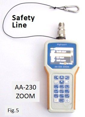
I soon purchased a RigExpert "AA-230 ZOOM" (scanning) antenna analyzer, anxious to finally measure the true impedance of various antennas.
I devised a Field Test, then began measuring; Boy was I surprised!
On the next two pages, I will show the results measuring two antennas: a mono-band 40m dipole, and a multi-band 40m Off-Center-Fed dipole. In each case I have measured the impedance and plotted an SWR curve across each band, when measured:
- Directly at the antenna's feedpoint
- At the end of an electrical half-wavelength of RG-58 coax (on 40m)
- At the end of a random length of coax (in this case 15m of RG-174)
On the 3rd page I will summarize and discuss the findings.
Here is a sneak preview:

In the graph on the left, when the feedpoint is near 50 Ohms, all three measurements are nearly identical at the frequency of minimum SWR (SWRmin). Near the ends of the bands, the SWR rises and the three curves drift apart.
In the curve on the right, the feedpoint impedance is not 50 Ohms. In this case, all three curves are quite far apart. Unless we measure the antenna directly at its feedpoint, we really have no idea of its true impedance.
For exact details, see the next three pages.
Avoiding Disaster: Be sure to use a safety line on the analyzer to prevent it from falling to the ground. Mine is made of 1mm Kevlar rope. Click on image below to enlarge photo:


Rome wasn't destroyed in a single day!