PAGE CONTENTS:
- The 2 Antennas and various Feedlines
- The 8 Antenna Matchboxes
- Test Equipment
THE ANTENNAS:
ANTENNA #1: 92 ft. long Horizontal Dipole:

The Dipole is perhaps the most commonly used antenna in amateur radio. Prior to World War II, it was usually fed with openwire (ladder-line) feedline. The common version was usually resonant on the lowest band for which it was to be used. When coax later became available at affordable prices, the ham community began referring to this antenna as a "Doublet", and the coax version as a "Dipole."
L.B. Cebik, W4RNL (SK) described this antenna in detail in a document The All-Band Doublet.
Several commercial antenna matchbox manufacturers ("OEM's") produced symmetrical matchboxes for use with these antenna, including DECCA, Harvey Wells, Johnson Viking, and much later Annecke. However, none of these OEMs exist today.
It was determined that shortening the length of the antenna (e.g., 110 ft. for 80m and 55 ft. for 40m) reduces the impedance on even harmonic bands. Unfortunately, space available for the antenna often determines which size doublet we can use.
Shorter versions (i.e., 88 ft./44 ft.) can work well, but are much more difficult to match. Depending on feedline length they may also create high loss in the matching network.
The antenna used here (92 ft.) approximates the 88 ft. version.
The most common matchbox circuit today is the T-Network, derived from the Ultimate Transmatch. In an effort to keep the price low, modern versions have variable capacitors with insufficient capacitance to enable a broad impedance matching range. Thus, often it is necessary to vary the feedline length in order to find a length that the matchbox can match. This is accomplished with feedline extensions.
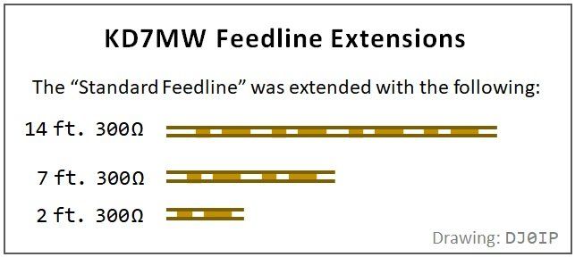
Feedline Extensions:
In order to present a selection of impedances to the antenna matchboxes, the overall length of the feedline was adjusted by adding combinations of the feedline extensions.
This was mostly done when testing the Vertical Dipole.
ANT #2: 40 ft. Vertical Dipole

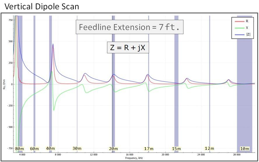
The Analyzer Scans below show the HF Bands for each of the 5 different feedline lengths used in this Shootout:
Click (left graph) to open the first graph (0 ft.), then on the right side, click the arrow rapidly to scroll through 2 ft., 7 ft. and 14 ft. graphs. Watch the curves shift with different feedline lengths.
This
Short Vertical-Dipole is one of the simplest multi-band antennas there is. It may even be used on 80m, but with considerably more loss than on higher bands.
L.B. Cebik - W4RNL (SK) described a similar but slightly shorter version in his article
A Vertical Doublet for 30-10 Meters. Additional information about this longer version is found on my web site here:
Simple Multi-Band Vertical .
This longer version performs better on the lower bands (i.e., 80/40m). Although making it even longer would improve performance on these bands even more, a total length of about 12m is the longest the antenna may be, before the 10m vertical radiation lobe splits into multiple lobes.
The feedline may be 600 Ohms, 450 Ohms, or 300 Ohms. In this case, the 7 ft. 300 Ohm extension was used to bring the feedline into the house. It is not a requirement for the antenna.
THE ANTENNA MATCHBOXES
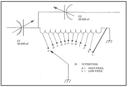
This is the standard
High-Pass-T Network. It has two variable capacitors in series with a single tapped/switched inductor in the middle, shunting to ground. With just 208 pF, its two capacitors are a bit shy on capacitance which may limit its impedance matching range.
Click Thumbnail ->
DECCA KW EZEE MATCH
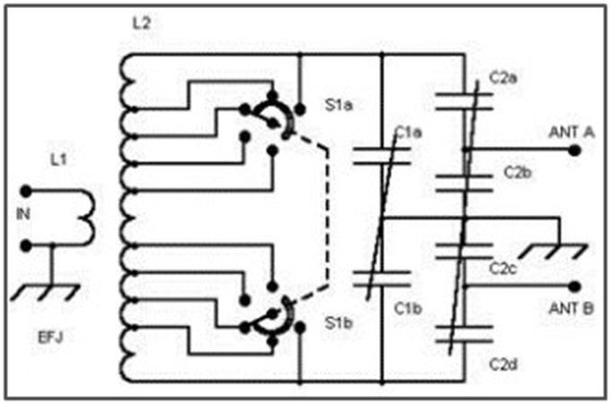
This is a popular 2-coil Z-Match from the U.K. It has only two controls, both variable capacitors. It also has two sets of output terminals, one for the low bands (i.e., 80/40m) and one for the high bands (i.e., 20-10m). 30m is sometimes better on one set, and with other antenna systems better on the other set of output terminals. Click Thumbnail ->
JOHNSON VIKING MATCHBOX
This is the famous Link-Coupled matchbox built 60 years ago. It was deemed the non-plus-ultra matchbox for matching openwire-fed antennas . . . back then. This test will show if is still the King of Openwire today! Click Thumbnail ->
(Referred to simply as "Matchbox" in the test results)
TEN-TEC Model 238A/B
The models A and B are identical, except for the color of their enclosure. The circuit is a Modified L-Network. Fundamentally it is an L-Network with the capacitor switchable to the input side of the coil for low impedance matching, or to the output side of the coil for high impedance matching. It has a 500 pF variable capacitor to which additional banks of capacitance may be switch in parallel to increase the impedance matching range.
The matchbox has 4 modes of operation. In addition to the two normal L-Network modes of operation,
- it can compensate for very low impedances by switching a tiny inductor into the circuit, or
- by switching a tiny capacitor into the circuit, it compensate for very high impedances (see far right photo). Click Thumbnail ->
(NOTE: the matching circuit is identical to the 238C)
THE ( EXTERNAL) BALUN
There is a lot of confusion about what type of balun should be used for the "Tuner Balun", and whether it should go on the input (TX) side of the matchbox or on the output (ANT) side of the matchbox.
The 1:1 Guanella (Current) Balun
MUST connect to the output side of the matchbox,
between the antenna feedline and the matchbox.
TYPE OF TUNER BALUN:
SEE: https://www.dj0ip.de/balun-stuff/tuner-baluns/
AND be sure to follow the links at the bottom of the page to comments by G3TXQ, VK1OD, and W8JI.
WHERE THE BALUN CONNECTS:
SEE: TUNER BALUN WHERE?
AND see VK1OD's comments (again), especially his final point in his CONCLSIONs at the end of the topic.
The balun used in this test is:
1:1 Guanella (current) balun:
- 18 turns of RG-58 Coax
- Wound contiguous (not cross-wound)
- (it may also be cross-wound if you prefer)
- Around an Amidon FT-240-43 toroid,
- and mounted in a plastic enclosure.
It is necessary to use a balun external to the enclosure of the matchbox; otherwise it is typically mounted too close to the metal cabinet, which can distort its balance.
Care must be taken not to place the external balun directly on top of the matchbox. This is not much better than mounting it inside of the matchbox.
In order to assure adequate spacing between the balun and the metal enclosure of the matchbox, we enlisted the help of a famous Russian author: Leo Tolstoy -->
More on simple tuner baluns:
https://www.dj0ip.de/rf-cmc-chokes/different-kinds-of-chokes/d2-guanella-choke/
(second half of that page)


THE TEST EQUIPMENT
The following test equipment was used in the Shoot-Out:
- RigExpert Model AA-54 Antenna Analyzer
- MFJ Model 834 RF Ammeter Click Thumbnail ->
NOTE: Yes, the MFJ-835 RF Ammeter with dual meters would have been better for measuring balanced line, but due to the current supply chain problems, the 835 was not available anywhere.


