
HOW CM CURRENT AFFECTS A BASIC DIPOLE
I ran extensive field tests in 2013 measuring Common Mode Current on the feedline for various antennas in various configurations, with 100 Watts of RF Carrier applied.
For each configuration, after recording the measured amount of CM Current, I replaced the transceiver with a RigExpert AA-54 scanning antenna analyzer, scanned the band being tested and recorded the data/image.
The idea was to identify how various amounts of CM Current affect the shape of the SWR curve, as well as the level of measured SWR.
I intentionally introduced CM Current into the antenna system by skewing the coax feedline radically to one side and then to the other side. The results were basically the same, regardless of which side I skewed the coax to.
Several engineers worked with me in the planning and preparation for the tests, including Steve Hunt, G3TXQ (SK), David Cutter, G3UNA, and Dr. Hartmut Hess, DJ1AT.
The data shown on this and the following pages of this
section of my web was taken from my 2013 CMC TEST.
SYSTEM FLOATING (above ground):
Although the idea was to begin with a basic dipole antenna, for logistic reasons I had to erect the dipole in an Inverted-V configuration. I'll show photos of the installation in the Photo Gallery for this section.

The system was made floating by using A.C. and D.C. Common Mode Current Chokes, designed by Ian White, GM3SEK. Photos are in the Photo Gallery (later). The RF Ammeter is an MFJ-854.
In preparation, brainstorming with Steve, we agreed that maximum CM Current should be at about 95% if a physical half-wavelength down the coax. We used a Velocity Factor (vf) of 0.95. We agreed that minimum CM Current would be at odd multiples of a quarter wavelength along the coax, using a vf of 0.95.
Although the coax had a vf of 0.66, this only applies to the differential current flowing inside of the coax. CM current flows on the outer surface of the coaxial shield and has a different vf. We estimated it to be what a thick wire would be, or about 0.95. Steve later ran more tests and found it to be about a full physical wavelength. For the measurements here, it didn't matter because the amount of CM Current does not change much with 5% more coax.
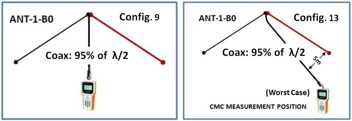
As seen from the text in the chart below, ANT-1 is a basic 40m INV-V, B0 is no balun at all. In the lines showing the amount of Common Mode Current, C.9 means configuration-9, C.13 means configuration-13, however, in the photo above showing the transmitter and ammeter, the configurations were designated 3a and 4a. The CM Current shown is the important point to focus on, not the labeling.
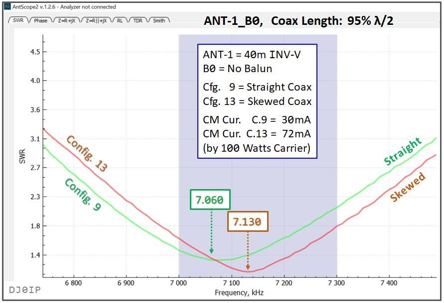
MOST IMPORTANT POINTS TO UNDERSTAND: The graph shown above is typical of how CM Current always affects antennas on their fundamental frequency:
- A low level of CM current does not cause any apparent skewing of the SWR curve. Indeed, throughout this extensive test (500 pairs of measurements), CM Current below 30mA never made any apparent difference in the shape of the curve.
- Above a certain threshold (approximately 30mA), CM Current begins to skew the frequency of minimum SWR higher up the band. The higher the level of CM Current, the farther up the band it skews.
- The level of minimum SWR changes. Whether it is higher or lower depends on the frequency you are measuring at.
- As the amount of CM Current increases, the curve flattens out, making the antenna look more broad-banded.
- As the CM Current increases even more, eventually it causes a double-dip in the level of SWR, as you shall see in the measurements on OCFD antennas with a Single-Core 4:1 Guanella balun.
SYSTEM GROUNDED:
The next test was to see if things improve or degrade when we ground the transceiver.
Although I repeated ALL tests made above and many others which are not shown here, the interesting tests are the ones where there is a fair amount of Common Mode Current on the feedline.

We would "think" that nobody in their right mind would erect their antenna like this. The feedline should be run at a 90 degree angle to the antenna. In real life, that is sometimes impossible. The amount of Common Mode Current induced onto the feedline will vary, depending on the angle at which the coax is run. For my test measurements, I tested it with a fairly radical angle. See photo in the Photo Gallery.
This first graph (below) contrasts the amount of CM Current with a straight coax to the increased amount of CM Current and the skewing of the SWR curve when the coax is run radically to one side.

Whereas the "floating" tests shown on the previous page saw a shift in the frequency of minimum SWR by just 70 kHz when radically skewing the coax to one side, in the identical test shown above, but with the transceiver grounded, the frequency of minimum SWR shifted 140 kHz up the band.
The graph below is more interesting. Both curves are with radically skewed coax. The curve in green is with the system floating. The curve is red is with the system grounded at the radio.

I find the results shown above to be quite shocking! When Common Mode Current is present, there is a huge difference in the amount of CM Current, depending on whether the system is grounded or floating.
On the other hand, with a good clean installation (i.e., the coax is running 90 degrees away from the antenna), the difference is almost negligible:

As seen in the graph above, the Common Mode Current with a floating system was 30mA and attaching the ground to the system only caused an additional 30mA of CM Current to flow. The curves of the SWR are very similar, but you will not a slight flattening of the curve when grounded. As stated on the introduction page, CM Current causes a flattening of the SWR curve.
SUMMARY OF ALL OF THE ABOVE
In a perfect installation, uncluttered by surrounding objects such as buildings, metal obstacles or other antennas, Common Mode Current is not much of an issue for a center-fed dipole antenna...
with one Caveat: Receiver Noise. I will address this at the bottom of this page.
In less than perfect installations, Common Mode Current will flow on the transmission line, even with so- called "balanced antennas".
When Common Mode Current flows on the transmission line, whether coax or balanced-feedline, the transmission line itself becomes part of the antenna and this skews the characteristics of the antenna.
Common Mode Current on the transmission line causes a flattening of the SWR curve across the band. To the casual observer, this may look like a better, more broad-banded antenna; but it is not. The level of SWR may be higher or lower, depending on the frequency you measure it at.
The frequency of minimum SWR as well as the frequency of resonance will change, with both skewing higher in frequency up the band. The higher the level of CM Current, the greater the skewing.
In (close to) perfect installations there may not be much difference in the level of SWR nor the level of CM Current between a floating system and a grounded system.
In less than perfect installations, such as surrounding objects or skewing of the coax away from a 90 degree angle to the antenna, CM Current can rise quickly, especially when no balun is used. It rises significantly quicker when the system is grounded, instead of floating.
Because the path to ground and the characteristics of the local ground, result can and probably will vary from one location to the next. To be on the safe side, it is always better to plan for the worst and take the necessary steps to reduce the risk (i.e., use a good balun).
RECEIVER NOISE DUE TO COMMON MODE CURRENT
We often hear hams claim that they have no issues with Common Mode Current. Some even claim they have no Common Mode Current on their antenna system. In fact there is always CM Current on the antenna systems, though it level is often so low that there are no noticeable issues.
Receiver Noise can also be caused by CM Current on the antenna feedline. In many cases it can be significantly reduced by using a good current balun at the antenna feedpoint. Sometimes an additional choke is required at the shack end of the coax.
I strongly recommend you take 3 minutes
to watch this short and informative video
on how a balun can reduce receiver noise:
The Effect of a 1:1 Balun on a Resonant Dipole