EC-OCFD: 500 WATT VERSION

(Dimensions are in Meters.)
This was my first attempt to build an EC-OCFD antenna.
It took quite a while to determine the best position for the feedpoint along this half-wave "Hertz" antenna. It was found by using an EZNEC model of a 40m OCFD, and then lots of "trial and error".
WHY it differs from that of an OCFD:
- In a standard OCFD, both wire legs are built using the exact same wire.
- In the EC-OCFD, the wire thickness of the outer surface of the coaxial shield is different from that of the wire leg.
How the best feedpoint position is determined:
Like with the OCFD, the 20m and 15m bands move in opposite directions when adjusting lengths. If we shorten the overall length, one band's resonance goes up, the other goes down. And Vice Versa. As a result, we have to adjust lengths for the best compromise in SWR between 20m and 15m.
The same is true when searching for the best feedpoint position.
Adjustment was complicated since changing the length of coax is more difficult than changing the length of the wire segment of the antenna.
I began with a feedpoint position 21% from the 1:1 Guanella Choke-Balun, leaving plenty of excess wire on the far end, folded back at the insulator and wrapped around itself.
After measuring the SWR curves on all bands (and recording), I shortened the coax segment of the radiator such that it was now 20.5% from the Guanella. Remeasured and recorded.
I shortened the coax again such that it was 20% from the Guanella. Remeasured and recorded.
I repeated this process in steps of 0.5% until it was just 17% from the Guanella.
I determined that
18% was the best compromise of all positions.
I removed the coax segment of the radiator and replaced it with a new piece of coax, such that the feedpoint was 18.1% from the Guanella. (Close enough!) Voila!
---------------------------------------
In this build, the coax stub for connecting to the antenna is only about 10 cm (4 in.) long. You can extend it to the shack with any length of 50 Ohm coax.
In order to have the frequency of minimum SWR inside of the harmonic bands, it is necessary to trim the overall length such that minimum SWR on 40m is below the band. The capacitor in the middle of the overall length of the radiator raises the resonance of the antenna on 40m, without changing resonance on higher bands.
A high-Ohm "bleeder" resistor of a few Meg Ohms, 3 Watt is shunted across the capacitor to protect it from static electricity.
I have given this capacitor/resistor device the name "Remote Matching Unit" (RMU), since its value determines the frequency of minimum SWR.
The advantage of this antenna over an EFHW antenna is, it moves the feedpoint farther away from the shack, thus reducing the feedpoint impedance to near 200 Ohms and reducing the amount of Common Mode Current at the feedpoint.
The shield of the coax begins radiating at the feedpoint's 4:1 Ruthroff UNUN and radiation is terminated at the 1:1 Guanella (choke) BALUN.
The coax between the Guanella BALUN and the shack does not radiate.
This was later proven in tests. See: https://www.dj0ip.com/efhw-vs-ecocfd
Photo Gallery:

The TX36/23/15/4A11 Toroid is strapped to an FR4 (epoxy board) backplane. The L-Adaptor and the insulator are optional, for use when erected as an Inv.-V antenna. When erected as an Inv.-L they are not required. (Ferrite similar to #43).
This 1:1 Guanella easily ran 600+ Watts in SSB and CW in my 80m OCFD Antenna.
I tested the 4:1 UNUN using the configuration on the right. I sent "dahs" for 10 minutes as slow as my keyer would send. It did not even get warm at 500 Watts.
For my initial testing, I erected the ECOCFD in an Inverted-V, so that I could compare its SWR and performance to my standard 40m OCFD. The shape and heights shown in the drawing on the right are fairly close to that of my 404-UL OCFD.
Note: although the antenna analyzer is directly connected to the 1:1 Guanella BALUN, that is NOT the feedpont. The antenna's feedpoint is at the 4:1 Ruthroff UNUN about 13 ft. (3.8m) away from the analyzer. Thus, the analyzer's readings do not reflect the exact impedances at the feedpoint.
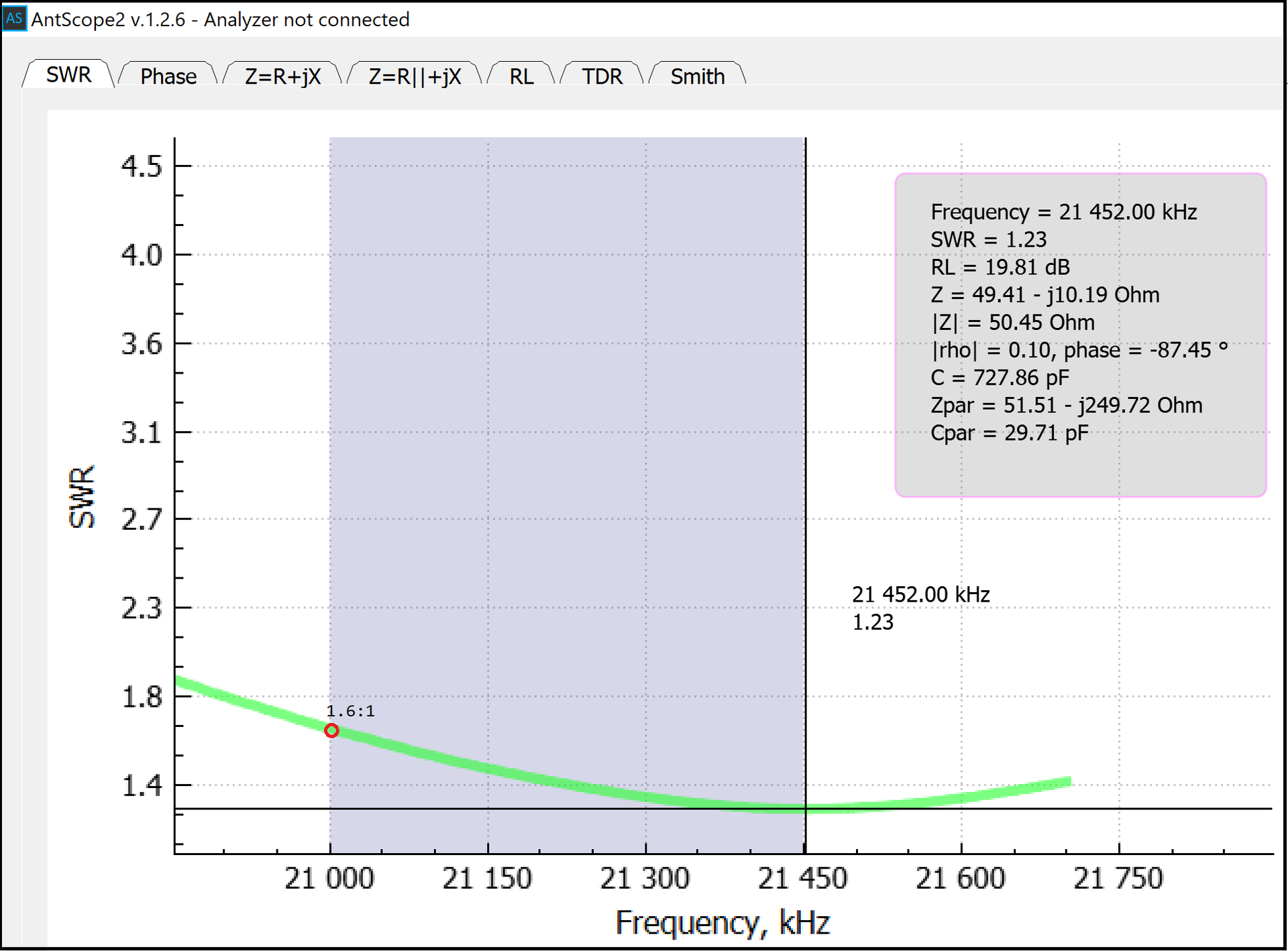
The graph on the right shows the SWR curves across the HF spectrum.
The SWR on the classic HF bands is excellent, but not on the WARC bands.
- 17m & 12m are useable with an Antenna Tuner
- 30m SWR is very high; if used with a Tuner, performance will be lower than on the other bands.
OTHER CONFIGURATIONS:
INVERTED-L:

I was unable to measure the EC-OCFD in this configuration because I am currently unable to erect a second pole to support the end.
LAZY INVERTED-L / LAZY INVERTED-V

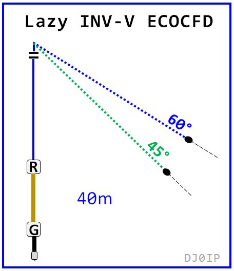
I tested the antenna in both configurations; 60 deg. had the best results. The results and more info are posted: HERE
Like with any Inv-L antenna, the lengths of the vertical and horizontal segments may be adjusted to adapt to the height of your pole/support. Of course change the shape changes the SWR curves on all bands slightly.
In a nutshell, these two configurations need only half the space of a horizontal dipole and deliver about the same performance.
Note: Once I had determined the final details of the antenna, it was very easy to replicate. As of May 2025, at least 15 people (that I know of) have built this antenna and they all work immediately with just minor adjustments to the length of the wire segment of the radiator.
However . . . the road to the final solution was long and rocky! The three sub-pages that follow show the problems I ran into with versions 1, 2, and 3. In the end (version 4), it was a complete success!


