
OCFD ANTENNA MODELING
Traditional (classic) OCFD antennas have used the "1/3 - 2/3" feedpoint split.
Indeed, most antenna books show this feedpoint position when describing OCFD antennas.
- But Why?
- Is it the Best Position?
The original concept of the OCFD antenna was to find a point along the half-wave antenna where the impedance of the fundamental and its even harmonic bands was the same, and then feed it with a balun that matched this impedance.
Sounds good, just one problem: this concept neglects the odd harmonic bands, specifically 15m! Indeed, 15m is a very important hf band to have. Why neglect this band when designing an antenna?
There are a couple of companies in the states (i.e., Radio Works and Balun Designs) that "claim" the OCFD does not and cannot cover 15m. They "claim" that it only works on that band due to "lossy coax". Clearly these dinosaurs of the past do not understand how and why the OCFD antenna works. It is simply a matter of where we place the feedpoint.
As it turns out, there are other feedpoint positions that have a good SWR on 15m, without losing coverage of any of the other classic hf ham bands. In fact, if we choose the right feedpoint position, an 80m OCFD can also cover the 30m band with low SWR.
BUT WHERE ARE THESE FEEDPOINTS? HOW DO WE FIND THEM?
The answer is simple: with the help of antenna modeling software.
The first product we will look at is EZNEC... not the program, rather just some results.
This web site is about practical solutions; thus you will not fine a course on how to model, but rather a page or two where you can view finished modeling results.
John Young, K8BA has modeled 160m, 80m and 40m OCFD antennas, showing results for a feedpoint impedance of:
- 50 Ohm
- 100 Ohm
- 150 Ohm
- 200 Ohm (most often used)
- 300 Ohm
AND
- for about 100 different feedpoint positions, from 0 to 50% along the half-wavelength wire.
In addition, each modeled antenna shows 3 sheets of results:
- Detailed impedance across each band
- Average SWR across each band
- Highest SWR within each band
Basically, this is all the information we would ever need when planning an antenna.
The trouble is, it is MORE information than most people care to deal with.
I have spent dozens of hours manipulating data in these files, and studying the results.
I will summarize my findings in another section under OCFD.
For now, here are the files.
OCFD Modeling Software, by DL1VU & DG0KW
In his Book published in 2000 by Theuberger Verlag GmbH, entitled Windom- und Stromsummen Antennen .(Eng. "Windom and Current Sums Antennas"), Karl Hille, DL1VU (SK) described his intensive study of the single-wire fed and 2-wire fed Windom antenna. He then suggested a different design goal for the 2-wire fed Windom (a.k.a. OCFD).
As I have never seen this antenna described in the English language, I have taken the liberty to give the
Current Sums Antenna the nickname "CSA".
Instead of feeding the antenna at a point where the impedance on the fundamental and all even harmonic bands are the same, he suggested feeding the antenna at a point where all bands of interest fall within a range of impedance that is acceptable for our transmitters. - i.e., SWR > 3:1. He described a method of finding this point by using the sum of the currents of all of the desired bands; thus the name, Current Sums antenna.
Using this program, let's examine why 15m does not work with the classic "1/3 - 2/3" feedpoint split, and take a look at what we must do to enable the antenna to work on 15m:
Reminder: The Impedance (measured in Ohms) Equals Voltage / Current ( R = E / I )
- If the current is low, impedance is high
- If the current is high, impedance is low
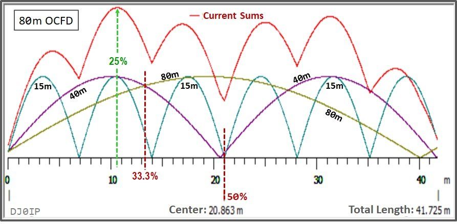
With an 80m dipole, the current is highest in the middle (50%). We know it has a typical impedance of 50 to 70 Ohms, depending on height. However, on 40m and 15m, the current is very low (nearly zero). Therefore the impedance is sky high (in practice it is a few kilo-Ohms.); thus the SWR is sky high!
At the feedpoint of a classic 80m OCFD (i.e., 33.3%), the 80m and 40m current curves intersect; thus their current is about the same, and their impedance is about the same. However, the 15m current curve at this point is very low. Thus its impedance and SWR is very high. This is why an 80m OCFD fed at 33.3% does not work well on 15m.
If we would move the feedpoint to the 25% point, the three current curves are close together - as clearly seen in the peak of the Current Sums (red curve). Thus, we would have high current on all three bands and relatively low SWR on all three bands.
- Their currents are not all equal, but all fall into a usable range.
- Thus, the antenna will work just fine on 80, 40, & 15m.
It is no coincidence that the optimum feedpoint position is exactly the point where the current sum of the three bands of interest is at its highest peak. Thus the name: "Current Sums Antenna".
The example above shows how easy it is to move the feedpoint to bring the 15m band into a useful range.
Clearly, the balun and OCFD vendors who claim this antenna cannot work on 15m,
simply do not understand how this antenna works.
In practice, we also want the antenna to work on 20 and 10m, and the 25% feedpoint is not a good choice. There are two good choices that give us all 5 bands (20% and about 29.5%). Which of these two we choose will also depend on which WARC bands we want to include in the antenna. More on this, elsewhere in the OCFD section of this web site.
In his book about Current Sums antennas, DL1VU published a DOS program that calculates current sums peaks, based on several user-definable parameters. Unfortunately the command lines had to be entered manually. Thus I never tried the program.
In 2010, DG0KW wrote a Windows-based program, based on DL1VU's DOS program. This one is a simple download and installation; then you're good to go. As you see in the example above, it is very easy to look at just about anything of interest on the OCFD antenna using this program.