Matchbox Shootout for Balanced-Line-Fed Antennas
SHOOTOUT DETAILS & EXPLANATIONS
The purpose of the antenna matchbox is
to maximize the transfer of RF current
into the antenna system's feedline,
while minimizing feedline radiation.
The purpose of this Matchbox Shootout is to evaluate various antenna matchbox technologies used for matching balanced-line-fed antennas.
SIMPLIFIED TECHNICAL EXPLANATION OF THE SHOOTOUT
In this shootout, we will apply 50 Watts of RF power to the antenna matchbox and measure the amount of RF current transferred to the antenna system's balanced-line feedline. The greater the amount of current is, the higher the efficiency of the matchbox, and the lower the loss of power is within the matchbox.
In order for RF current to flow, we need two lines: one line to the antenna, and a second line providing a return path to the source. With balanced line feedlines, we have two lines; let's call them A and B.
- During the first half cycle, current flows to the antenna on line A and returns on line B.
- During the second half cycle, it reverses; current flows to the antenna on line B, returning on line A.
In a perfect world, at any point along the feedline, the amount of current flowing in each of the two lines is equal, but opposite in polarity. We refer to this a differential current and say that it is "in balance" when equal to zero.
- Whenever it is in balance, the feedline does not radiate.
- Whenever it is out of balance, i.e., there is more current in one line than in the other, the feedline effectively becomes part of the antenna and radiates.
When comparing the various antenna matchboxes,
besides measuring the amount of RF current out,
we will also measure the balance in RF current
between each of the two lines of the feedline.
The efficiency of any matchbox depends on several things, including its circuit design, the quality (i.e., "Q") of its components, as well as the impedance of the antenna system and the frequency at which it is measured.
All antenna matchboxes tend to have lower efficiency (thus higher loss) when matching very low impedances. At very low impedances, there are significant differences in efficiency between the various matchbox circuits.
The Effect of Feedline Length on Impedance:
Whenever the impedance of the feedline is not EXACTLY the same as the impedance of the antenna at its feedpoint, the impedance of the antenna system varies with the "electrical" length of the feedline.
In that case, the feedpoint impedance is repeated at every electrical half-wavelength along the feedline. At each quarter wavelength of feedline, and odd multiples thereof, the feedpoint impedance is inverted. In other words, a high impedance becomes a low impedance, and vice versa.
Electrical half-wavelengths and quarter-wavelengths are short on higher bands, but very long on lower bands. For this reason, most of the measurements with varying impedances were made on the higher bands, rather than on the lower bands.
A SAMPLE OF MEASURED RESULTS

EXPLANATION OF EACH COLUMN:
Matchbox:
This column shows the name of each of the 8 antenna matchboxes tested. It is ranked from "best" (at the top) to "worst" at the bottom. A description of each matchbox is found on the Components page of this shootout.
= = = = = = = = = =
Freq:
This column shows the frequency (in MHz) used for this group of tests.
= = = = = = = = = =
MEASUREMENTS:
ALL measurements were made while running 50 Watts of output
power from an ICOM IC-7300. (It's power setting was "52".)
Note: Each combination of antenna/frequency/feedline-length will present a different impedance to the point of measurement.
Impedance is the ratio of voltage to current:
- High impedances mean: low current/high voltage,
- Low impedances mean: high current/low voltage.
Therefore, a measurement of 0.4 amps RF current one one band is not necessarily worse than 1.8 amps on another band, or on the same band but with a different antenna/feedline-length combination. Meaningful current comparisons can only be made when freq./ant/feedline-length are the same.
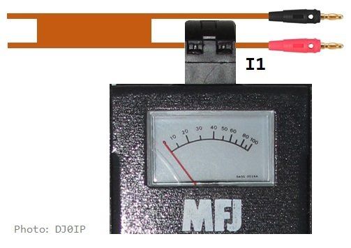
I1:
This column shows the RF current measured (in Amperes) in one of the two wires of the balanced feedline. The higher this value is, the more RF power is being transferred to the feedline; thus, the lower the internal power loss in the matchbox.
= = = = = = = = = =

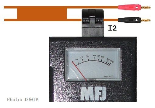
I2:
This column shows the RF current measured (in Amperes) in one of the two wires of the balanced feedline. The higher this value is, the more RF power is being transferred to the feedline; thus, the lower the internal power loss in the matchbox.
= = = = = = = = = =

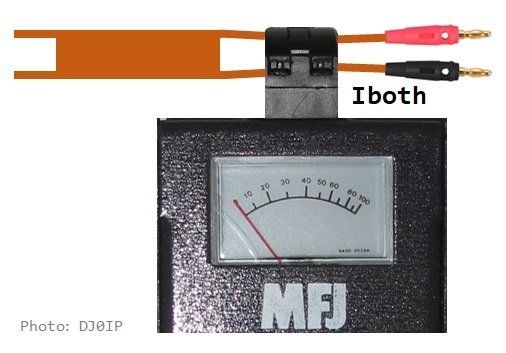
Iboth:
This column shows the RF current measured (in Amperes) across both feedline wires at the same time. Best case, the current in both wires are equal, but opposite polarity; thus, the net value is zero (0). A reading higher than zero indicates an unbalance in the currents; thus it shows the amount of Common Mode Current present. Therefore, a lower number is better.
= = = = = = = = = =

Dcurr:
Simple Description: (Differential Current) This value represents the effective amount of current delivered to the feedline. In most cases it is approximately the average of I1 and I2; (i.e., (I1+I2)/2).
Technical Description: We used a more accurate method which also includes phase angles. This was calculated by "borrowing" the formula out of Owen Duffy's (VK1OD) - thanks Owen - java script calculator program on his blog page Measuring Common Mode Current. However, as you will see, in most cases it was very close to the value derived from the simple description above.
= = = = = = = = = =
Rel. Effic.:
Relative efficiency takes the highest average current, expressed as a percentage, sort from highest to lowest and marked 100% green to let the eye see breaks between blocks of frequency. Percentages of 85% or greater are shown in GREEN. Lower percentages mean increased loss and heating in the matchbox.
= = = = = = = = = =
UnBal:
"Unbalance": shows Abs(I1-I2)/Max(I1,I2), expressed as a percentage. Basically it is taking the absolute value of the difference between I1 and I2, dividing it by which ever of the two currents is greater, and expressing it as a percentage. Zero indicates no match. Unbalances greater than 10% are marked in RED.
= = = = = = = = = =
%CMC:
Measured Iboth/Max(I1,I2), expressed as a percentage. Zero indicates no match. CMC levels greater than 10% are marked in RED.
= = = = = = = = = =
Antenna:
This shows the antenna currently being measured, and the length of feedline extension (if any). In the example shown above, the antenna is the vertical dipole with its initial 70 ft. of 450 Ohm balanced-feedline, +7 ft. of 300 Ohm feedline. The tests were conducted in groups. The number preceding the antenna name is the group number of the test. Each time a different antenna or different feedline length was used, a new group number was assigned to the test.
= = = = = = = = = =
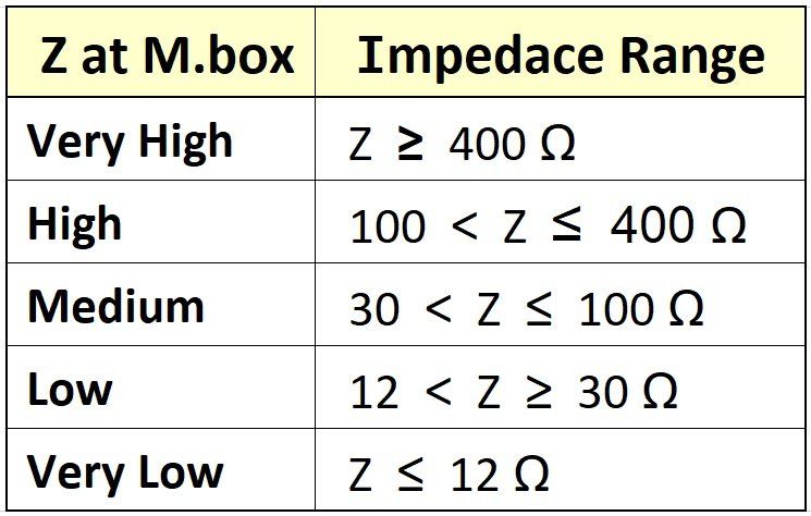
Z at Matchbox:
This shows the approximate impedance presented by the antenna system (i.e., the antenna, its initial feedline, plus feedline extension).
= = = = = = = = = =

