MEASURING OCFD ANTENNAS
This section pertains only to OCFD antennas.
It is not about measuring antennas in general.
The OCFD is a very special multi-band antenna. It requires no traps or loading coils, etc. It is known as being a "harmonic" antenna, but it isn't really. Simple math shows that it is not.
EXAMPLE: 80m OCFD Antenna, cut for minimum SWR (SWRmin) at 3.700 or 3.800 MHz:

Unless we cut the antenna for the CW/Digi portion of 80m, the harmonics are above the higher bands.
In order to have the SWRmin of higher harmonic bands fall within the band, we must cut the antenna to have SWRmin on 80m below the band:

- The chart above shows real life "measured" results.
- "corrected" shows the results after shortening the antenna.
- Remember: SWRmin is a frequency, not an SWR value.
- The reason harmonics are higher than 2x,3x, 4x, etc. is due
to "End-Effect" acting differently on each band.
Notice that SWRmin falls low in the 20m band, and much higher in the 15m band. When pruning the overall length of the antenna, it is important to monitor these two bands and cut the antenna for the best compromise in SWR for the two bands - disregarding the frequency at which 80m SWRmin occurs.
IMO, the introduction of a scanning analyzer is the greatest boon to being able to successfully build a multiband antenna. Unfortunately, most people continue to use them wrong.
EXAMPLE: A Scan of an 80m OCFD over the Full HF Spectrum

The graph above "looks nice", but tells me practically nothing about the band-specific details of the antenna. All I can see is that the SWR is good or close to being good on several bands.
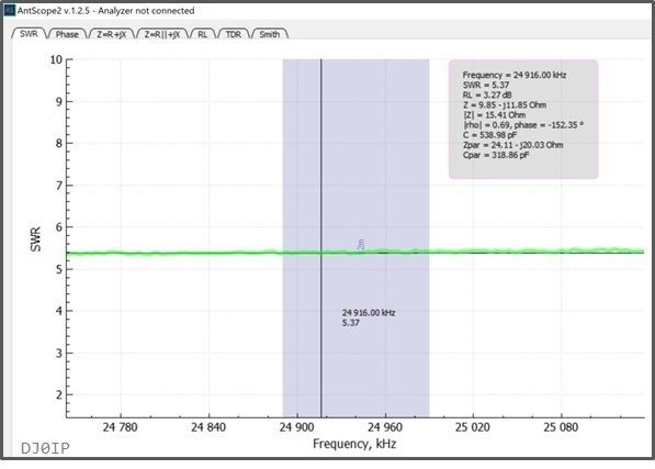
In order to see what my antenna is really doing on each band, I have to perform a bandspread scan across each band. I typically make a 1 MHz scan, centered on each band, except 10 where I make a 3 MHz scan and 6m where I make a 5 MHz scan.
See Below:
The two tables on the right show recommended scans for evaluating OCFD Antennas.
These are shown in the format required by typical scanning analyzers such as the RigExpert models AA-55 ZOOM, AA-230 ZOOM, AA-650 ZOOM, and the Stick 230.
The scan is defined by entering a center frequency and "half" the scan width depicted as +/- (in kHz).

This gives me detailed information on each band. An example of a 40m OCFD I measured recently is shown below in the photo gallery:
With individual band scans, we are able to locate the exact frequency where minimum SWR (SWRmin) occurs on each band. THIS information is necessary for tuning and optimizing the antenna for the best-compromise of SWR on all bands.
More on this in the "Tuning OCFD" page in this section (under construction).


