
MEASUREMENTS: STAKE-IN-THE-GROUND
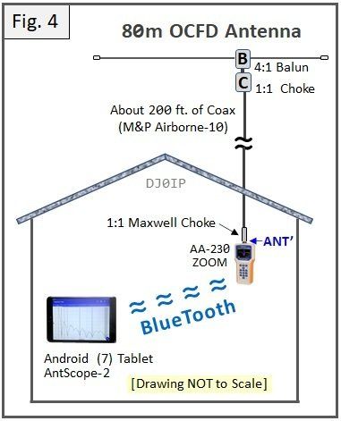
Since I cannot currently measure outside, due to the February winter weather, I have chosen to use the shack-end of the coax to my 80m OCFD antenna as my virtual antenna feedpoint. I will refer to this as ANT'.
The goal of this section (determining the impedance at the antenna feedpoint) will use ANT' as its virtual feedpoint. Different means of remote measuring will be investigated to see if they match the impedance measured when measuring directly at ANT'.
The BIG QUESTION: just how should we measure and define our stake-in-the ground ?
I have considered 3 possible methods:
1) Floating: The coax from the antenna ends with a Maxwell choke (in the shack). The analyzer . is connected to the end of the coax. There is no direct or indirect connection to ground inside of . the shack.
2) USB: The analyzer is connected to the end of the coax and also connected to the computer . through a USB cable. The computer is also connected to the radio. The computer and radio are . powered off of the mains.
3) USB + Coax:
Like 2 (above), plus the shield of the coax to the radio is connected to the coax
. connector barrel of the analyzer. The places the shield of the analyzer at the same potential to
. ground as the radio.
This drawing shows the 3 measuring possibilities:
"Floating", "USB", "USB+Coax"
The different remote methods are shown below:

R+C = Radio + Computer


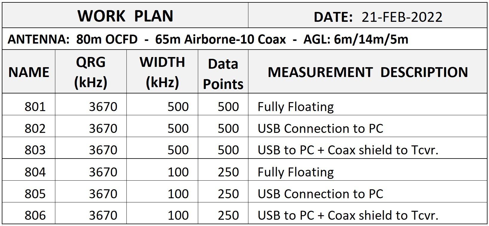
Measuring all of these different scenarios, labeling and saving each file is no easy task. Because the differences were so small, it was very easy to confuse the data. Before even beginning, I made a plan for what was to be measured, then followed the plan.
This sounds simple enough but altogether it was about 6 hours of work, including documenting and uploading to this web page.
1: Floating
The analyzer was connected to
ANT'
(only). No further connections.

2: USB
The analyzer was connected to
ANT' and via USB to the computer.

3: USB + Coax
Same as #2, and the coax shield was connected to the analyzer shield.

All three results were very close together. Floating SWRmin was just 2kHz lower than the other two.
I paused about 2 hours for lunch; and then it rained. I measured again:


The wet ground below the antenna did not change much. The level of SWR remained about the same, the frequency of SWRmin dropped 4 to 6 kHz
I was surprised that there was so little difference in all of these measurements.
During the morning (before the rain), I made a more "bandspread" measurement for each of these, hoping to see more detail by reducing the space between measurement data points.


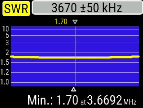
These scans were made centered on the approximate frequency of SWRmin, +/- 50 kHz. As you see, they are all within 9 kHz of each other. The level of SWR was the same (1.7:1).
Next, we will evaluate the BANDWIDTH of SWRmin:
When measuring every half kHz, we find the level of SWR is oscillating by 0.01 often across the bandwidth of minimum SWR. However, it also oscillates on the rest of the curve.

Floating:
The SWR was oscillating between 1.70:1 and 1.71:1 from 3654.4 to 3684.0 kHz; a total of 29.6 kHz.
The SWR was oscillating between 1.71:1 and 1.72;1 from 3644.4 to 3696.4 kHz; a total of 49 kHz.

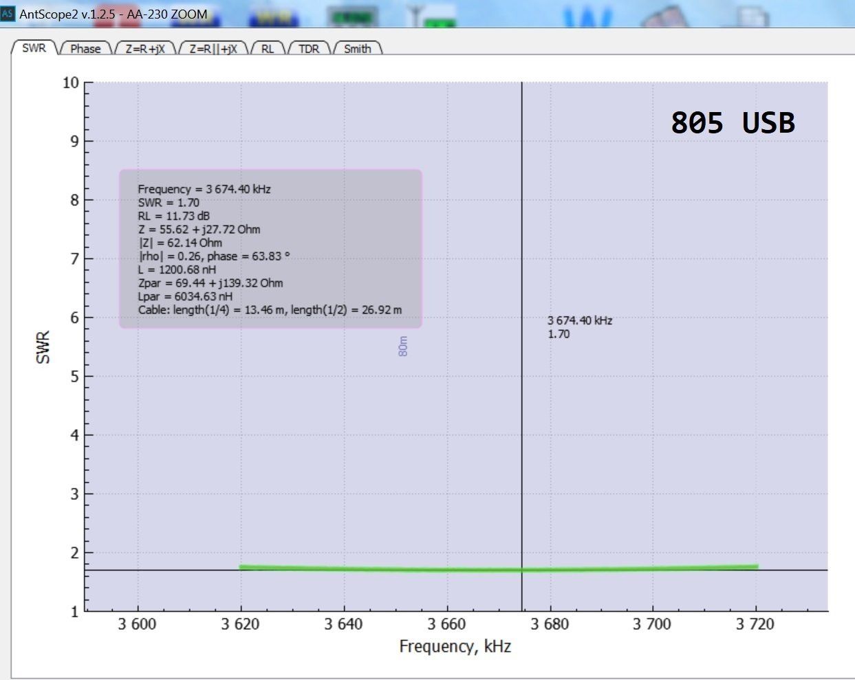
USB:
The SWR was oscillating between 1.70:1 and 1.71:1 from 3652.0 to 3686.0 kHz; a total of 34 kHz. This is even broader than when Floating (above).
The SWR was oscillating between 1.71:1 and 1.72;1 from 3643.2 to 3692.2 kHz; a total of 49 kHz. The bandwidth is the same as when Floating (above).
USB + Coax
The SWR was oscillating between 1.70:1 and 1.71:1 from 3656.0 to 3672.0 kHz; a total of 16 kHz. The bandwidth when measuring like this is much narrower.
The SWR was oscillating between 1.71:1 and 1.72;1 from 3646.0 to 3692.8 kHz; a total of 46.8 kHz. The bandwidth is only slightly narrower.
Note: I like this one best!

DISCUSSION:
The purist may argue that there are differences in these three methods of measuring, but for the average amateur radio operator it is peanuts. Keep in mind that my feedline is choked often between the antenna and the shack, and its shield is also grounded along the way in two places. The results might vary a bit more if the feedline were completely floating.
Stake-in-the-Ground: for my further tests with remote measurements, I shall use the USB+Coax method. I feel it most accurately represents the real life scenario, since this is how we actually operate the radio.
More important is that ALL measurements are conducted with the same configuration, and made at the same time, not hours or days apart. This means, before attempting any remote measurements, I will repeat the stake-in-the-ground measurement and record for reference.