
THE INVERTED-L ANTENNA (Inv-L)
Most people have probably heard of the Inverted-L antenna before. As stated on the previous page, it consists of both vertically polarized radiation and horizontally polarized radiation. How much radiation of each type depends on the shape of the Inv-L. There are 3 possibilities, shown on Fig.1-3 below.

In Fig-1, when we make the vertical segment longer and the horizontal segment shorter, vertically polarized radiation increases and horizontally polarized radiation decreases.
In Fig-3, when we make the vertical segment shorter and the horizontal segment longer, vertically polarized radiation decreases and horizontally polarized radiation increases.
A Simplified Explanation about Efficiency:
There are 3 components we must consider:
- Radiation Resistance
- Ground Resistance
- D.C. Resistance in the Radiator
RADIATION RESISTANCE (RR) is that part of the electrical resistance at the antenna's feedpoint that is caused by the emission of radio waves from the antenna. In other words, this is a good resistance.
In a full-size vertical or Inv-L antenna, radiation resistance is typically 36 Ohms.
GROUND RESISTANCE (RG) is the loss caused by the ground beneath the antenna. Ground resistance can vary from very low values of 5 ohms, up to more than 100 ohms (5-30 ohms is a frequently quoted range). The RF power dissipated in the ground resistance is not available for radiation. We can lower ground resistance by improving the radial network below the antenna.
D.C. RESISTANCE IN THE RADIATOR (RD.C.) is the resistance of the radiator wire itself. Since the radiator is usually made of copper or aluminum, it is typically just
1 Ohm or so. As such, in our simplified look at efficiency we will ignore .
REMEMBER: what's below the antenna is as important as the antenna itself.

This chart shows some typical examples of how important a good ground (i.e., radial network) below the antenna is.
One way to improve the amount of radiated power is to improve the radial network below the antenna, thus reducing ground resistance.
For more info on radials and links to research work on radials, see: RADIALS.
OPTIONAL: Improving Efficiency by Raising the Radiation Resistance
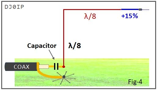
Raising the Radiation Resistance will also improve the antenna's efficiency. This is accomplished by increasing the overall length of the antenna by about 15%. It makes no difference whether we increase the length of the vertical segment, the horizontal segment, or both.
The idea is to raise the radiation resistance from 36 Ohms to 50 Ohms.
However, increasing the length by this amount will lower the frequency of resonance by 15%. The resonant frequency can be raised back to its desired frequency by inserting a capacitor between the center conductor of the coax and the radiator.
Insert a capacitor between the center conductor of the coax and the radiator. Very Simple.
The value of the capacitor determines how high resonance is raised. This will vary depending on the band the antenna is built for as well as from one QTH to the next. This value must be found empirically. I use a variable capacitor to find the value, and then replace it with a fixed capacitor.
Assume we have a very efficient radial network below the antenna with 10 Ohms.
- With 36 Ohms radiation resistance, the SWR was 1.06:1. (i.e., 50 Ohms / total resistance) and our efficiency was 76.6%.
- With 50 Ohms radiation resistance, the SWR is now 1.22:1 (i.e., somewhat worse), but our efficiency is now 82%.
- Although the SWR is higher, the the radiated power is also higher.