
BASIC DEFINITIONS
Brief definitions of important terminology for this Matching Balanced-Line Fed Antennas:
- Basics Definitions:
- What is a "Balanced-Antenna"?
- What is "Balanced Transmission Line"?
- What is a "Balanced ATU"?
- What is an "Unbalanced ATU"?
- How to feed Balanced Line with an unbalanced ATU.
What is a "Balanced-Antenna"
Actually, this is a trick question.
A "Balanced-Antenna" is not just an antenna whose two halves are physical identical. This is no assurance that the antenna is
electrically
balanced.
More important is that the two halves are balanced in impedance to the ground below it.
THIS is very rare here on Mother Earth, unless the antenna is over Salt Water.
In Urban Areas, where houses are very close together, having a truly balanced antenna is next to impossible. There are simply too many objects around creating reflections of RF.
In addition to objects in close proximity to the antenna, height above ground and consistency of the ground below the antenna influence the balance.
In practice, the best we can do is understand what physically balanced and physically unbalanced antennas are. Here are some examples:
PHYSICALLY 'BALANCED' ANTENNAS:
- Center Fed Dipole Antennas
- Center Fed Inverted-V Antennas
- Full-Wave Loop Antennas
PHYSICALLY 'UNBALANCED' ANTENNAS:
- Vertical Antennas
- Off-Center-Fed Dipole Antennas
- End-Fed Antennas (EFHW, EFRW)
What is "Balanced Feedline"?
The correct name is "Balanced Transmission Line".
It consists of two identical wires with spacing provided in various forms (as seen on the right).
People often confuse the names, but as you see, there are distinct differences Ladder-Line, Window-Line, and Twin-Line.
Although Window-Line is generally considered to be 450 Ohms, it actually comes in various impedances, depending on the thickness of the wire.
See:
https://www.dj0ip.de/open-wire-fed-ant/openwire-info/
Each type has advantages and disadvantages.
What is a Balanced ATU?
A "Balanced ATU" (a.k.a. "Symmetrical ATU") is an ATU specifically designed for matching Balanced-Line Fed Antennas.
There are several different designs of Balanced (Symmetrical) ATUs:
- Link Coupled
- Balanced-T
- Balanced-L
- Balanced-Pi
- Zed-Match
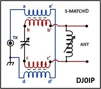
- S-Match (new)
The various circuits are shown on the right. For some of the circuits there are 2 or more versions. In that case I only shown one here for simplicity.
Each design has advantages and disadvantages.
Read about the advantages and disadvantage on my web, here:
https://www.dj0ip.de/antenna-matchboxes/symmetrical-matchboxes/
THE MYTH ?
Many claim the Link-Coupled ATU is the best way to match a Balanced-Line Fed Antenna.
In this project we shall see how a Link-Coupled ATU compares to other technologies.
The S-Match shown on the right was not an after-thought. I could not fit it onto a single screen of the computer together with the other ATUs, without making all of the ATUs's schematic very small. So it is shown here alone.
The ANNECKE schematic on the right is the same for both the 200 Watt and 1 kW versions of the ANNECKE SYMMETRISCHE KOPPLER.
Of course, the size of the box and the components is significantly larger in the 1 kW version.
The four variable capacitors shown on the far right are one very large "double-differential" capacitor.


What is an Unbalanced ATU?
Most ATUs currently (2025) available on the new equipment market are Unbalanced ATUs.
Unbalanced ATUs are primarily used to improve the match to Coax-Fed Antennas.
The various circuits are similar to the ones shown above, but somewhat simpler (and cheaper).
The common technologies are:
- T-Network
- L-Network
- Pi-Network
In addition, some hams also use:
- Zed-Match (same circuit as above)
- S-Match (same circuit as above)
Choose any circuit and compare it to its balanced circuit above. You will see that the balanced version has at least one or more components than the unbalanced version.
EXAMPLE: T-NETWORK:


These are all quite simple compared to the more complex Balanced Circuits. And of course they are much cheaper.
How to feed a Balanced-Line with an Unbalanced ATU:
The best practice is to always use an External 1:1 Guanella (Current) Balun together with unbalanced ATUs to feed the Balanced Feedline.
The balun is simple and easy to home-brew. The one I used in the test has 12 turns of twisted-pair transmission line wound onto a Ferroxcube TX36/23/15-4A11 Toroid, similar to an FT-140-43).
CAUTION: Many ATUs have a built-in 4:1 Balun.
These should NEVER be used.
The tuner MUST be a 1:1 current balun.

THE BOTTOM LINE: Using a home-brew external 1:1 Current Balun together with a low-cost unbalanced ATU is a LOT CHEAPER than purchasing a balanced ATU. Unless there is a significant improvement in efficiency/balance/phase, there is no reason to waste money on a balanced ATU.
THE PURPOSE
of this research is to determine if the advantage of a balanced ATU is worth the extra money.