
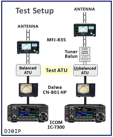
THE TEST SETUP
The IC-7300 was set for an output power of 60 W.
It was powered by an Astron P.S.
(No Extra Ground)
It was connected to the Daiwa Watt meter with a 50cm piece of Aircell-7 coax.
The Watt meter was connected to the ATU under test via a 1m piece of Aircell-7 coax.
The Balanced ATU was connected to the MFJ-835 RF Ammeter via 85cm of Ladder-Line.
The
Unbalanced ATU was connected through a Home-Brew Tuner Balun and the Ladder-Line to the MFJ-835.
The Ladder-Line to the antenna was terminated in a
RED and a
BLACK banana plug, so that I could identify its two different wires.
THE ANTENNA

The ideal test would use at least three different antennas; Very Low Ohms, a few Hundred Ohms, and a couple Thousand Ohms.
Fundamentally, this is accomplished by testing the antenna on many bands. It is very low impedance on 80m (i.e., about 22 Ohms), and the impedance rises on higher bands.
I used "THIS" particular antenna for two reasons.
First, I already had it pre-built in my junk box. It had been previously used as a vertical dipole at my QTH in Oklahoma.
Second, it has very low impedance on 80m.
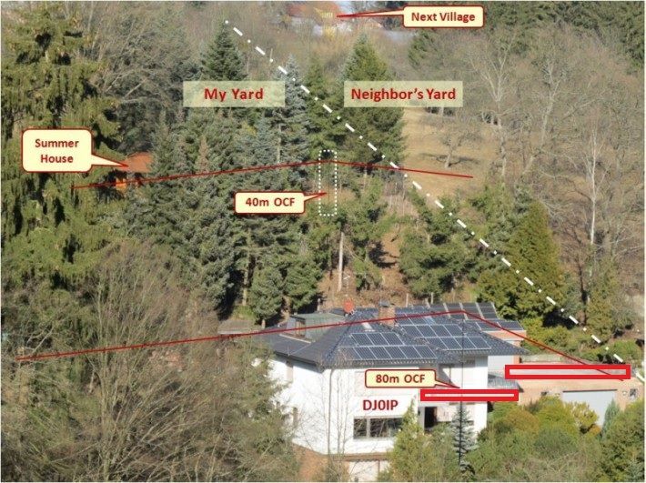
OBVIOUSLY my QTH is less than perfect for an antenna test. Living in the Main-Spessart National Park, we are surrounded by mountains and forests. I had no other QTH to run my test.
The antenna in this photo is an 80m OCFD, not the test antenna. I erected the test antenna in its place, with both ends equally high above ground.
The Ladder-Line runs fairly straight to a table on the patio, just below the right side of the left
Red Rectangle in the photo.
There is a metal guard-rail on the wrap-around balcony upstairs. This is most likely detrimental and perhaps reacting with the antenna on some bands (especially 15m, as you shall see).
CALIBRATING THE DUAL-METER MFJ-835 RF AMMETER
I had planned to purchase a NEW MFJ-835, but MFJ went out of business before I did. As a result, I had to look for an MFJ-835 on the used market. Luckily, I found one and bought it.
Anxious to begin my tests, I setup the station outside on the patio. I was shocked to see how unbalanced my antenna was, even though physically, it looked fairly balanced.
READ THE INSTRUCTIONS RICK!
The instructions describe a calibration procedure. I ran the procedure. When I opened the box to adjust the two meters, I found a sticker indicating the instrument was built in 2012 - 13 years ago. (Duh!)
After calibrating the two meters, things looked MUCH better!
Lesson Learned: BEFORE beginning any field test, always check the calibration of the instruments!
A second thing I learned is, reversing the two leads of the Ladder-Line changes all the readings. As a result, I attached a RED banana plug to one side and a BLACK banana plug to the other side, so that I would be sure to measure all ATUs the same way when recording measurements.
Here are the SHOCKING results found during the calibration procedure:
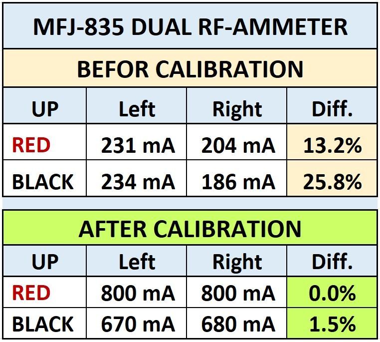

HOLY COW!
No wonder the antenna looked so unbalanced!
Lesson Learned: Always check instrument calibration BEFORE beginning a Field Test!
HOW I MEASURED RF CURRENT
As you will see, reversing the connection of the balanced feedline changes all of the measurements. This is the procedure I followed:
- In order to be sure I measure each ATU in the same way, I attached a RED Banana Plug to one wire and a BLACK Banana Plug to the other wire of the feedline.
- I began with the RED Plug on the upper terminal of the Ammeter, the BLACK Plug on lower terminal.
- I applied a 60 Watt Carrier to the ATU and recorded the amount of RF Current measured on each of the two wires.
- Then I reversed the connection of the feedline to the Ammeter; Black Plug on the upper terminal, RED plug on the lower terminal, and measured and recorded again.
- I measured each band this way and recorded my measurements.
As a result, I have two sets of measurements on each band for each ATU.
HOW I DETERMINED THE POWER IN THE FEEDLINE
The ARRL has tested several ATUs over the years and my TEN-TEC 238-B is one of them. In that test, it was determined that the 238-B has less than 10% loss when matching very low impedance on 80m.
I "assumed" an efficiency of 95%. Knowing the applied power minus 5% loss, I calculated the output power. Since the current in the two lines was not equal, I used the average of the two current measurements for my calculation. Using Power and average RF Current, I then calculated the impedance to be about 22 Ohms.
Knowing the impedance to be 22 Ohms, and the average RF current in other ATUs, I calculated the output power of the ATUs to the feedline.
Margin of Error: Plenty, I guess, but it is likely within 10%.
Using the calculated power for each ATU on each band and comparing it to that of the 238-B, I am able to rank all of the tuners in order of efficiency. (Lots of work and I have only just begun.)