
EC-OCFD: 150 Watt Version

Note: I will insert exact measurements as soon as I get a helper to help me measure each segment with a long tape measure.
WHAT IS IT?
Basically, it is an OCFD antenna, but uses the outer surface of the shield as the short side of the radiator, rather than a dedicated wire.
The shield of the coax begins radiating at the feedpoint's 4:1 Ruthroff UNUN and radiation is terminated at the 1:1 Guanella (choke) BALUN. The coax between the Guanella BALUN and the shack does not radiate.
The EC-OCFD was measured as an Inverted-V because I was unable erect it as flat-top antenna:

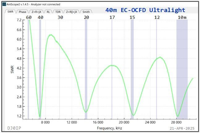
See more SWR curves (by band) in the Photo Gallery below.
The advantage of the EC-OCFD antenna over an EFHW antenna is: it moves the feedpoint farther away from the end of the antenna, thus reducing the feedpoint impedance to approximately 200 Ohms.
As a result, this significantly reduces the amount of Common Mode Current at the feedpoint, on the coax, and in the shack!
This "End-Connected Off-Center-Fed Dipole" is just like my 500 Watt version on the previously page, except it uses smaller components and handles less power. It is an ultra-light-weight antenna for my day-outings on my motor scooter. 80m coverage is not needed.
This version weighs just 217 grams (7.8 oz.).
In order for the frequency of minimum SWR to be inside the harmonic bands, it is necessary to trim the overall length of the antenna such that minimum SWR on 40m occurs below the band.
In this case it is at 6.797 MHz.
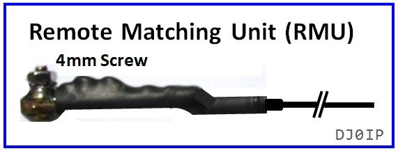
To raise the frequency of minimum SWR on 40m up into the band, I inserted an
RMU in the exact middle of the antenna. The capacitance of the RMU has negligible affect on the frequency of minimum SWR on the harmonic bands.
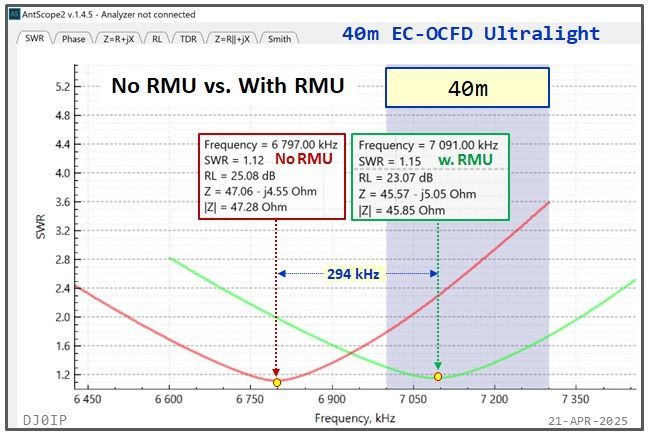
The amount of capacitance of the RMU (Remote Matching Unit) determines where minimum SWR will fall on 40m. I have set mine near the center of our Region-One 40m band (7.091 MHz).
The capacitors must only handle a couple hundred volts, but they must be able to handle a fair amount of RF current. To achieve this, I used 3 disc ceramic capacitors in parallel. Using multiple smaller capacitors instead of one single large capacitor enables you to adjust the frequency in small steps.
Not shown but absolutely necessary: a high Ohm (4 Meg, 4kV) bleeder resistor is shunted across the RMU capacitors to protect them from static electricity. It's resistance value is not critical. Anything from 1 to 5 Meg-Ohm may be used.
PLAN B:
The most critical component in the EC-OCFD is the 1:1 Guanella Choke-Balun. It must have sufficient Common Mode Impedance (CMI) to completely top the coax shield from radiating between it and the shack.
In an effort to make the antenna as lightweight as possible, I began by using a single FT-114-43 in the choke. It turned out that this choke had insufficient CMI and I had to re-design it.
From my previous build, a 500 Watt EC-OCFD balun, I determined that its choke (17 turns of RG-316 on a single FT-140-43) has sufficient CMI. But it was a lot heavier.
My next step was to wind the choke onto a stack of two FT-114-43 Toroids. I measured the antenna and determined this to be good enough... and it saved 42 grams of weight.
HOW DID I KNOW IT WAS GOOD ENOUGH?
(Thought you'd never ask - hi)
Through my hundreds of hours of field tests measuring CM Current with an Ammeter and observing how different amounts of CM Current affect the SWR curve of the antenna, I discovered that it always skews the resonant frequency as well as the frequency of minimum SWR (which I call "SWRmin").
I have charts comparing SWRmin of OCFD antennas for a dozen different baluns, as well as baluns + additional choking. I determined when adding additional choking to any balun, if the resonant frequency changes, or the SWRmin changes, the balun previously did not have enough CMI. AND, once the addition of more choking no longer changes Resonance or SWRmin, the balun alone was good enough.
I also determined that CM Current up to about 30 to 40 mA on the feedline, though measurable, makes no visual difference in the shape of the SWR curve. And, SWRmin only moves 10 kHz or so.
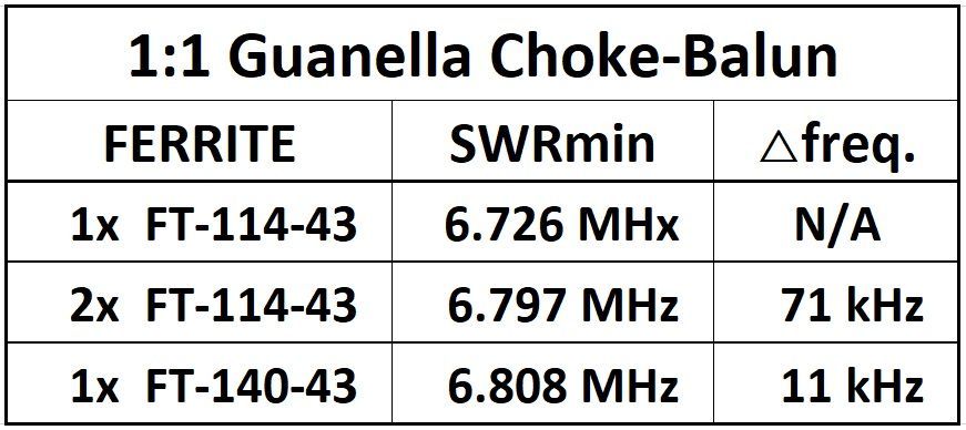
This chart shows the frequency of minimum SWR on the fundamental band (40m) for the three different chokes.
Using 2x 114's raised SWRmin by 71 kHz. This was just 11 kHz below the SWRmin of the choke with the FT-140. "Close Enough".
You won't read this in any book! It is the result of the experience I have acquired from 12 years of research and over 3000 field measurements of OCFD antennas.
I ran a CM Current Comparison Test between my 500 Watt version of the EC-OCFD and three commercial EFHW antennas in 2024. I erected each antenna as a "Lazy Inverted-L" onto a 12m tall Spiderbeam fiberglass pole located just 4m (13 ft.) away from the large window in my shack.
Results: All three EFHW caused significant RFI issues in the shack with just 15 to 20 Watts of power, whereas with 500 Watts of transmitted power into the EC-OCFD there were no RFI issues in the shack at all.
It was clean as a whiste!
Photo Gallery: COMPONENTS
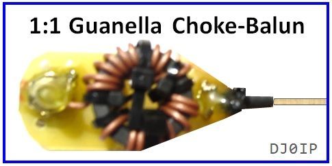

The Guanella Choke-Balun consists of a stack of 2 FT-114-43 Toroids cross-wound with 17 turns of RG-178, a very thin and lightweight, Teflon-insulated coax. Weight: 50g (1.8 oz.)
SWR Curve: click thumbnail below:

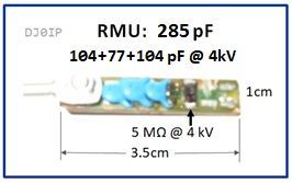
The RMU consists of 3 capacitors and 2 resistors. The resistors are stacked (piggy-back) creating 5M Ohms @ 4kV. They protect the capacitors from high voltage static electricity.
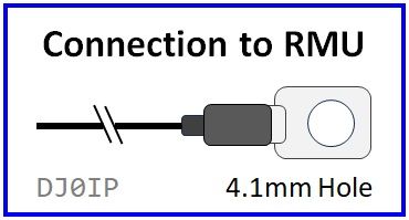
This solder lug connects the short segment of the long leg of the wire to the RMU. The long segment of the long leg has the RMU permanently attached to one end and the end-insulator to the other end.
Splitting the long leg into 2 parts makes it easier to wind up without creating a tangled mess!
Portable operators will appreciate this feature!
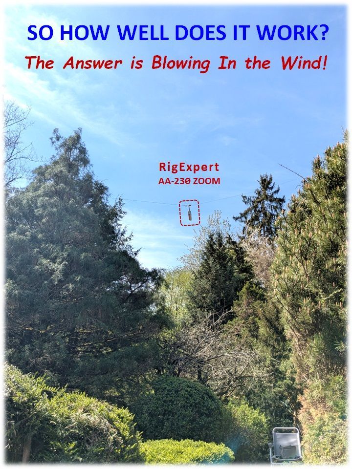
To find out, I hung my AA-230 ZOOM 4 meters in the air and measured all bands directly at the 1:1 Guanella Choke Balun, using BlueTooth and my cell phone.
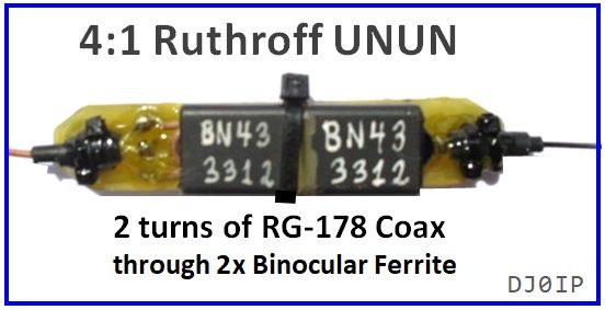
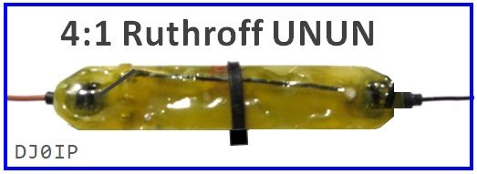
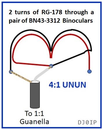
A pair of BN43-3312 binoculars are glued together and wound with 2 turns of RG-178 coax, a thin and lightweight Teflon-insulated coax, providing a 4:1 impedance match to the antenna.
An UNUN is used in order to induce Common Mode Current onto the coax shield.
Weight: 39g (1.4 oz.)
SWR Curve: click thumbnail below:

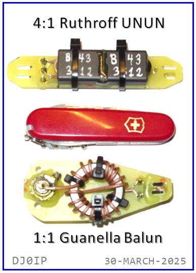
Here you see the size of the Balun and UNUN. Both are quite small and ultra-lightweight.
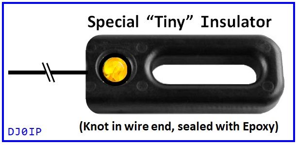
I made this insulator by shorting a "Mini-Insulator" and rounding the ends. The wire terminates inside of the round hole, secured by a knot. Epoxy glue from both sides seals and weather-proofs it.
Photo Gallery: SWR CURVES, by Band (Inverted-V)
(click on image)


OTHER CONFIGURATIONS:
INVERTED-L:

I was unable to measure the ECOCFD in this configuration because I am currently unable to erect a second pole to support the end.
LAZY INVERTED-L

I tested the antenna in both configurations; 60 deg. had the best results. The results and more info are posted: HERE
Like with any Inv-L antenna, the lengths of the vertical and horizontal segments may be adjusted to adapt to the height of your pole/support.
In a nutshell, these two configurations need only half the space of a horizontal 40m dipole and deliver about the same performance + also have very low SWR on 20, 15, & 10m. They may be used on the WARC bands using an antenna tuner.
Configuration Differences:
Obviously, the SWR Curve across each band changes a little when we change the configuration.
The graph on the right compares the SWR Curves of the INV-V configuration with the Curves of the Lazy INV-L with a 60 degree angle and a 45 degree angle.
Regardless of configuration, the SWR on the fundamental band (40m) remains under 1.8:1 across the entire band.

In each case, height above ground & the angle at the apex affects the SWR Curve on all bands.
Photo Gallery: SWR Curves, INV-V vs. Lazy-INV-L


The INV-L in the graphs above were made with a Lazy-INV-L with a 60 degree apex. I have all the measurements for the 45 degree apex as well. They are different but still very good.
As stated earlier, if we change the angle of the apex, the height of the antenna, or the QTH of the antenna, the SWR curves will vary slightly. These curves are representative of what you can expect to get, but yours may not be EXACTLY the same.
CONCLUSION:
I haven't yet taken this version to the field but I am fully confident it will work perfectly well. My 500 Watt version of this antenna has been copied and built by 5 other OM that I know of, and was the subject of an antenna seminar in Austria where 10 OM built it. All 10 antennas worked right out of the chute with just minor length adjustments.
APPENDIX:

Patience Please. After all, Rome wasn't destroyed in a single day!
And neither was the Berlin Wall, but I was there tearing it down:

Brandenburg Gate, West Berlin, Saturday, November 11th, 1989.
And that's not a beer in my hand; it's French Champaign, courtesy of Lufthansa!
It always bugs me when people say "the wall 'fell' down". It didn't just "fall down"; we tore that mother down with a passion! I pounded on the wall until the handle on my sledge hammer broke, then I flew home to Munich.
When I got to work Monday morning, my colleagues were all excited and asked me if I watched the wall being town down on TV.
I replied,
nah, I didn't watch TV on the weekend; I had something better to do!
BTW, I'm wearing my original U.S. Army field jacket and jump boots that I wore when serving in Berlin from January 1972 until March 1974. Those were the only original army clothes that still fit! (hi)
For those of you who may not know, Berlin at the time was located 100 miles
behind the Iron Curtain.
DOWNLOAD INV-V FILES
(120 degrees apex)
DOWNLOAD LAZY-INV-L FILES
(60 degrees apex)